Zinc Coating on Galvanized Pipe: Thickness, Testing, and Service Life
A zinc thickness reading is useful only when it is assessed against the correct pipe specification, measurement method, and acceptance rule. A coating that passes one standard is not automatically suitable for another application, and even a conforming coating does not guarantee a particular service life in an unknown environment.
The zinc coating on galvanized pipe protects steel both as a physical barrier and through sacrificial action when small areas of steel are exposed. Its durability depends on the coating actually present at vulnerable locations, the corrosiveness of the exposure, and whether fabrication or installation has damaged the surface.
What zinc thickness says—and what it does not
Coating thickness is generally reported in micrometres (µm). Some specifications instead express coating mass per unit area, commonly in grams per square metre (g/m²). For a zinc coating, the approximate conversion is:
Thickness in µm ≈ coating mass in g/m² ÷ 7.14.
For example, 500 g/m² corresponds to approximately 70 µm as an equivalent average thickness. This calculation uses the density of zinc and assumes that the coating mass and area refer to the same surface. Actual hot-dip galvanized coatings contain zinc-iron alloy layers, so the conversion is an approximation, not a substitute for the method prescribed by a standard.
The distinction between average and local minimum matters. A report showing a satisfactory average can conceal an isolated thin area. Conversely, a single low instrument reading does not necessarily establish nonconformity: the applicable standard may define a local result as the average of several readings within a reference area.
Thickness alone also says nothing definitive about coating continuity, adhesion, exposed steel, or inaccessible internal surfaces. Those characteristics require separate examination under the relevant specification.
Identify the governing standard before testing
“Galvanized pipe” can describe pipe galvanized after manufacture, pipe made from continuously coated strip, or pipe supplied to a specific structural, fluid-service, or other product standard. These routes do not necessarily use the same coating requirements. The purchase order should identify the applicable standard, edition, coating designation where relevant, and any project-specific requirements.
Several standards are frequently encountered, but their scopes are not interchangeable:
- ISO 1461 covers hot-dip galvanized coatings on fabricated iron and steel articles. Its coating requirements depend on the article category and steel thickness, and its inspection provisions distinguish local and mean coating thickness.
- ASTM A123/A123M covers zinc coatings on iron and steel products galvanized by the hot-dip process. Coating grade requirements depend on product category and material thickness; the standard also addresses inspection and repair.
- ASTM A53/A53M is a pipe product specification that includes requirements for hot-dip galvanized pipe when that finish is ordered. Its product-specific provisions should not be replaced by a generic coating requirement without checking the contract.
- ISO 2178 describes magnetic measurement of non-magnetic coatings on magnetic substrates. It is a test-method standard, not a complete pipe product specification or an independent statement of acceptable coating thickness.
A specification can incorporate a coating standard by reference, add stricter project requirements, or establish its own sampling and acceptance rules. The controlling documents must be read together. Compliance with one standard should not be presented as certification to another solely because both concern galvanized coatings.
For pipe, the specified inspection scope also needs to address the inside surface. Hot-dip galvanizing of finished hollow sections can coat both the interior and exterior where zinc can enter and drain, but exterior readings cannot establish the condition of the bore. For pipe formed from pre-galvanized strip, the weld area and any specified restoration deserve particular attention.
How coating thickness is measured
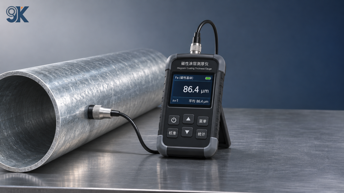
Magnetic thickness gauges
Magnetic gauges provide a practical, non-destructive way to check zinc on steel. A probe measures the effect of the non-magnetic coating between the instrument and the magnetic substrate. Results are affected by surface roughness, pipe curvature, proximity to edges, substrate thickness and magnetic properties, and the condition of the probe contact.
Before taking production readings, check the instrument’s calibration status and verify its performance with suitable reference standards. Adjustment on an uncoated sample of comparable material, curvature, and surface condition can reduce measurement bias. Foils or coated reference standards used for verification should span the expected thickness range.
Place the probe on clean, stable surfaces and avoid forcing it onto sharp edges or weld irregularities. Record individual readings or reference-area averages as required by the governing standard. A gauge reading taken on an accessible exterior surface is not evidence of internal coating thickness; bore measurements require suitable access and an appropriate instrument or another specified method.
Coating mass by stripping and weighing
A destructive stripping method determines coating mass by measuring the mass lost when the zinc coating is removed from a specimen of known surface area. ASTM A90/A90M is a relevant test method for zinc or zinc-alloy coating mass on iron and steel articles. The result represents an average over the tested area, not a map of the thinnest spot.
Surface area calculations need care for pipe samples: the result depends on which surfaces were coated and included in the calculation, including internal surfaces and cut ends where applicable. Stripping also does not establish adhesion or identify a small localized defect that has been averaged into a larger specimen.
Microscopic cross-section
A prepared cross-section can show coating thickness and layer structure at a selected location. It is useful for investigating disputed readings, unusual coating appearance, or adhesion-related questions. Because it is destructive and examines a very small area, it should not be treated as proof of uniformity across a pipe or lot.
No single technique answers every inspection question. Magnetic readings help map accessible surfaces; mass testing checks average coating weight over a specimen; microscopy helps investigate local structure. The chosen method and sampling plan must still follow the contract and applicable standard.
Sampling and surface inspection: where acceptance errors arise
A meaningful inspection plan starts with the lot definition: pipe size, wall thickness, production route, coating process, and traceability to the supplied documentation. Samples should be selected according to the governing specification rather than only from pieces with the easiest access or best appearance.
Measurement locations should represent the pipe surface and include areas where process or fabrication conditions could affect coating continuity, consistent with the standard. Pipe ends, weld regions, handling-contact areas, and other accessible features warrant visual attention. Measurements taken directly on an edge or rough weld may not be comparable with readings on the adjacent pipe wall, so the location and reason for each reading should be recorded.
Visual inspection remains essential. Look for uncoated areas, coating damage, excessive deposits that interfere with assembly, and surface conditions that may affect the intended use. A dull grey appearance or surface texture alone is not necessarily a defect; acceptability depends on the specified standard and whether the coating performs its required function. White corrosion products on stored galvanized surfaces require assessment of their extent and any associated coating loss rather than an automatic pass or rejection.
When a result is below a specified limit, distinguish an instrument reading from a formal test result. Check probe contact, verification records, measurement location, and the standard’s rules for averaging and retesting. Do not discard low readings merely to improve the mean. If nonconformity is confirmed, segregation, disposition, repair, or rejection should follow the contract and applicable standard.
Repairs, welds, and installation damage
Cutting, threading, welding, abrasion, and mechanical handling can remove or damage zinc. These areas may become the controlling corrosion locations even when the original pipe coating met its specified average thickness. Welded joints also need examination for areas affected by heat and for coating discontinuity.
Repair is not simply a matter of applying any zinc-rich paint. The governing specification may limit the size and number of repairable areas and prescribe surface preparation, repair materials, application, and minimum repair thickness. ASTM A780/A780M addresses repair of damaged and uncoated areas of hot-dip galvanized coatings; it should be used where specified and alongside the acceptance requirements of the product or project standard.
Repair coatings are not necessarily identical in composition or performance to the original galvanized layer. Their inspection should be documented separately, including the location, preparation, material, and measured dry-film thickness where required. Large or widespread uncoated areas should not be assumed repairable without checking the applicable limits.
Estimating service life without treating thickness as a guarantee
For atmospheric exposure, a simplified estimate can be expressed as:
Estimated time to a defined coating condition ≈ available zinc thickness ÷ assumed zinc loss rate.
As an illustration only, an available thickness of 70 µm divided by an assumed loss rate of 2 µm per year gives 35 years to consumption under that simplified model. Neither value is a universal design input. The calculation assumes a constant loss rate, ignores local defects and repairs, and does not account for changes in exposure. It is not a prediction of pipe failure or a warranty period.
ISO 9223 classifies the corrosivity of atmospheres, while ISO 9224 provides guiding values of corrosion rates for specified atmospheric corrosivity categories. These standards can support an atmospheric assessment, but the selected category must reflect the actual site and exposure. Sheltered areas that retain moisture or deposits can behave differently from open, well-drained surfaces.
Service-life assessment becomes more application-specific when pipe is buried, immersed, insulated, or exposed internally to process fluids. Soil properties, water chemistry, temperature, flow conditions, deposits, and the possibility of differential aeration can change corrosion behaviour. An atmospheric corrosion category should not be used as a direct substitute for an assessment of buried or internally wetted pipe.
The endpoint must also be defined. Time to first visible rust, time to a maintenance threshold, and time to unacceptable wall loss are different outcomes. Initial red rust at a damaged spot does not necessarily mean the pipe has lost its structural or pressure capacity; equally, a coating that looks acceptable externally does not establish the condition of the bore.
What a useful inspection record should establish
A defensible record links the pipe lot to the purchase specification and identifies the standard editions, sampling plan, instrument, verification checks, measurement locations, individual or averaged results, and applicable acceptance limits. It should distinguish exterior measurements from internal evidence and identify any areas not accessible for inspection.
Where repairs are accepted, retain their locations and inspection results with the original coating record. Where a service-life estimate is required, document the exposure assumptions and the defined endpoint separately from the coating conformity decision. That separation prevents a compliant thickness report from being mistaken for proof that the pipe will perform for a specified number of years in every installation.
Latest News
- How do iron ore prices affect steel pipe price trends?
- How do tariffs affect square tube export markets?
- How steel pipe price trends affect inventory valuation
- Steel pipe price forecast for 2026 amid changing raw material costs
- Square Tube Export News: What Buyers Should Watch in Freight and Supply
- What new trade investigations mean for steel pipe exports
Send Us A Message

