How to limit weld distortion in steel pipe for machinery frames
How to limit weld distortion in steel pipe for machinery frames
A machinery frame can look square before welding yet pull out of alignment as the joints cool, leaving operators with uneven mounting surfaces, assembly gaps, and costly rework. When working with Machinery Manufacturing Steel Pipe, limiting distortion starts before the first arc—with consistent fit-up, a balanced tack-welding plan, and controlled heat input. Weld sequence, suitable fixturing, and careful checks during cooling help reduce twisting and bowing without relying on excessive post-weld straightening.
The practical objective is not to eliminate weld shrinkage. It is to control where that shrinkage acts, keep movement within the drawing tolerances, and avoid storing excessive stress in a frame that only looks correct while clamped.
Understand which movement is causing the problem
Welding heats a small area while the surrounding pipe remains cooler and resists expansion. As the weld and nearby material cool, they contract. If that contraction is uneven around a joint or across the assembly, the frame moves.
On square and rectangular hollow-section frames, a weld concentrated on one face can pull a crossmember out of position. Several joints welded along the same side can accumulate enough shrinkage to bow a rail. Uneven heating between corners can introduce twist, leaving one foot above the inspection table even when the diagonals appear acceptable.
These symptoms need different responses. Matching diagonals helps assess rectangularity, but does not prove that the frame is flat. A straight rail does not guarantee that its mounting pads share a plane. Identify the functional requirement—rail straightness, bearing alignment, mounting-face flatness, or overall squareness—before changing the welding method.
Remove fit-up problems before adding heat
Start with the incoming sections. Check straightness, twist, wall thickness, and cut-end geometry against the purchase specification and fabrication drawing. Nominally identical pipe can still produce inconsistent joints if the actual dimensions vary or the ends are not cut square.
A joint with an excessive gap often needs more deposited metal and more heat. Forcing poorly fitted members together with clamps creates another problem: the assembly contains elastic strain before welding begins. When released, it can move from both weld shrinkage and springback.
Dry-assemble the frame on verified supports. Confirm member lengths, joint gaps, and corner angles, then check diagonals and relevant heights. Remove burrs and prepare the weld zone as required by the welding procedure. Oil, moisture, scale, and coatings can affect weld quality and make a consistent process harder to maintain.
Do not compensate for poor fit-up by increasing fillet size. If the specified joint cannot be assembled consistently, correct the cutting or preparation process before adjusting the weld.
Use tacks and fixtures to guide shrinkage—not hide it
Locate the frame from its functional datums. For a base supporting linear guides, those references may differ from the outside edges of the tubing. Support long members adequately, and position clamps so they restrain critical movement without blocking torch access or forcing an unsuitable welding angle.
Tacks should hold the intended joint gap and geometry through handling and welding. Their size, placement, and treatment must suit the material, joint, and applicable procedure. Tacks that will become part of the finished weld need appropriate quality; cracked or defective tacks should not simply be covered.
For a rectangular frame, distribute tacking around the assembly rather than completing one corner while the others remain unsecured. Recheck dimensions as the tack pattern develops. If a corner pulls during tacking, investigate immediately instead of assuming the finishing welds will bring it back.
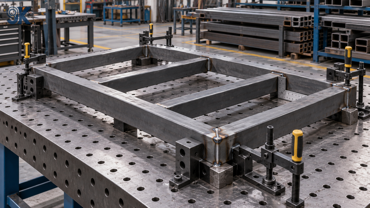
Heavy restraint is not automatically better. A rigid fixture may suppress visible movement while increasing residual stress. The result can change when clamps are removed or when mounting faces are machined. Fixture design should therefore include an agreed release sequence and an unclamped inspection, not just an in-fixture dimensional check.
Plan the weld sequence around the whole frame
A common cause of distortion is finishing every accessible weld on one side before turning the frame. That approach is convenient, but it concentrates shrinkage in one direction. A better plan distributes welding between opposing joints, faces, or subassemblies where access and the approved procedure allow.
For a simple rectangular base, the trial sequence might alternate between opposite corners, then between corresponding joints on the other faces. This is a starting principle, not a universal weld map. Joint stiffness, wall thickness, attachments, and handling arrangements determine whether it works on a particular frame.
Long welds may benefit from planned skip or back-step techniques. With back-step welding, individual segments progress in the opposite direction to the overall sequence. These methods require controlled starts, stops, and tie-ins; they are not permission to leave gaps where the drawing requires a continuous weld.
Write the sequence on a shop sketch. Include welding position, direction, inspection pauses, and when the frame may be repositioned. Otherwise, different operators may each use a reasonable local technique while producing an inconsistent overall result.
Use only the weld metal the design requires
Oversized welds add shrinkage without necessarily improving the joint’s useful capacity. Follow the specified weld size and length. If the drawing is unclear, obtain engineering clarification rather than adding a continuous heavy fillet “for safety.”
Intermittent welds can reduce total heat where the design permits them, but they may be unsuitable for fatigue loading, sealing, corrosion exposure, or hygiene requirements. Operators should not replace continuous welds with stitch welds solely to improve appearance or flatness.
Control heat input without sacrificing fusion
The aim is controlled heat, not the lowest possible machine setting. Insufficient energy or excessive travel speed can cause lack of fusion. Slow travel, oversized beads, and unnecessary weaving can increase local heating and distortion.
Use the applicable welding procedure to establish the process, consumable, current, voltage, travel speed, and any preheat or interpass requirements. Wall thickness, steel grade, joint geometry, and restraint all matter. A setting that works on a thick mounting bracket may be unsuitable for the thinner hollow section beneath it.
During production, watch for heat accumulation as well as individual bead quality. Repeatedly welding around one bracket can create a local hot spot even when each pass is acceptable. Moving to a distant joint may help distribute heat, provided the sequence and temperature requirements are maintained.
Do not improvise water quenching to recover dimensions. Uneven rapid cooling can introduce further distortion and may affect material properties. Likewise, hollow members need a safe venting arrangement where welding could heat an enclosed volume; never assume a sealed section is harmless.
Keep covers and mounting details from pulling the main structure
Secondary parts can undo a well-controlled frame. A thin guard panel welded continuously along a rail can bow the panel and pull the rail. Where the design allows, bolt-on covers or separate attachment tabs can isolate those effects and make maintenance easier.
If a drawing specifies DX51D+Z Galvanized Steel Plate for covers or enclosure panels, treat it as a separate material decision—not an automatic substitute for structural tubing or load-bearing brackets. Any welding requires suitable coating preparation, fume controls, and an agreed method of restoring corrosion protection. Mechanical attachment may avoid disturbing both the coating and the finished frame geometry.
Precision mounting pads deserve similar planning. Where as-welded tolerances cannot reliably meet the machine’s alignment requirements, the design may need machining allowance and post-weld machining. Trying to achieve a machined tolerance through clamping alone is rarely a dependable production method.
Measure while corrections are still manageable
Check the frame after tack-up, at planned welding stages, and after cooling and fixture release. Use consistent datums and support conditions. Measurements taken on a hot, clamped assembly should not be treated as final acceptance results.
- Check diagonals for in-plane racking, alongside member lengths and corner geometry.
- Check rail straightness independently of overall frame squareness.
- Check mounting-point heights or coplanarity to reveal twist.
- Inspect weld quality separately; acceptable dimensions do not establish adequate fusion.
If the same movement repeats, record where it begins. Early corner movement suggests a different problem from bowing that appears only after brackets are added. Change one controlled variable at a time—fit-up, sequence, restraint, or weld deposition—so the next trial produces useful evidence.
Mechanical or thermal straightening should follow an approved repair method. Uncontrolled hammering or flame heating can damage local geometry and compromise later alignment. Prevention is preferable, but a defined correction procedure is still necessary for nonconforming frames.
Make the successful method repeatable
Once a trial frame meets requirements, retain the cut list, material specification, joint details, tack arrangement, welding sequence, and inspection results. Repeatability depends on incoming material consistency as much as operator technique.
For externally sourced Machinery Manufacturing Steel Pipe, communicate straightness, dimensional tolerances, cut preparation, and identification requirements before ordering. Shandong Jiukai Metal Materials Co., Ltd., based in Shandong Province, combines custom production and deep processing with warehousing and export logistics. Its drawing-evaluation and specification-selection services can help align supplied sections with the fabricator’s actual fit-up requirements.
For a small trial batch or a repeat export order, the useful next step is the same: confirm the material, functional datums, allowable distortion, and inspection condition before production. A frame that meets tolerance after cooling and unclamping is a more meaningful result than one that only looks straight on the welding table.
Latest News
- How anti-dumping duties change market access for steel pipe exports
- How could electric arc furnace investment reshape steel industry development?
- How Steel Pipe Warehousing and Logistics Affect Damage Rates and Delivery Costs
- Seamless vs Welded Steel Pipe: Which Option Fits Budget and Lead Time
- ASTM and EN Standards for Carbon Steel Pipe in Pressure Systems
- When a Standard Steel Pipe Works Better Than a Custom Specification
Send Us A Message

