What Do Steel Pipe Solutions Include for Industrial Piping Projects?
Steel Pipe Solutions for industrial piping projects include pipe selection, production, fabrication, inspection, documentation, and delivery planning. The scope starts with the fluid, pressure, temperature, and installation conditions, then translates those requirements into pipes and prepared components that fit the intended system. Fittings, flanges, coatings, and testing belong within that scope when they are included in the agreed supply package.
A pipe that matches the requested diameter can still be unsuitable because of its material grade, wall thickness, dimensional tolerances, or end preparation. An effective solution connects these details before production, so that material arriving on site matches the design and the planned assembly method.
The supply scope starts with operating conditions
Industrial piping carries fluids under conditions that vary substantially between applications. Cooling water, compressed air, steam, lubricating oil, and process chemicals create different requirements for strength, corrosion resistance, cleanliness, and joining. Even the same fluid produces different selection decisions when its temperature, concentration, or flow conditions change.
The initial technical basis should identify design pressure and temperature, fluid composition, external exposure, and the applicable piping specification. Normal operating values alone are insufficient: startup, shutdown, pressure surges, and cleaning cycles can establish more demanding conditions. For vacuum service, resistance to collapse also requires consideration.
The physical arrangement matters as well. A straight pipe run between accessible supports presents different fabrication needs from a congested equipment connection with several bends. Vibration, thermal movement, nozzle loads, and access for welding or maintenance affect how the piping is designed and prepared. Pipe supply supports these decisions, while responsibility for system design must remain clearly assigned.
Material and pipe construction answer different questions
Carbon steel is widely used where its strength, temperature capability, and corrosion behavior suit the service. Stainless steel becomes relevant when the fluid or surrounding environment requires additional corrosion resistance or particular cleanliness characteristics. Alloy steel addresses other service demands, including certain elevated-temperature applications. These categories narrow the selection; the specified grade establishes the actual material requirements.
Stainless steel is not universally resistant to corrosion. Chlorides, temperature, deposits, and crevices can change its performance significantly. Likewise, selecting carbon steel requires a decision about expected corrosion and whether the design relies on additional wall allowance, internal lining, external coating, or another protection method.
Seamless and welded describe how pipe is manufactured. Neither description, by itself, establishes suitability for every pressure system. Acceptance depends on the material specification, manufacturing controls, weld quality where applicable, examination requirements, and the governing design rules.
Substitutions therefore need technical review. Matching outside diameter and nominal thickness does not establish equivalence when grades, delivery conditions, or testing requirements differ.
Dimensions must match the connection method
Nominal pipe size is a designation rather than a complete dimensional description. A usable specification identifies the dimensional system, outside diameter, wall thickness or schedule, length, and relevant tolerances. Mixing dimensions from different systems can create mismatched fittings even when the nominal size labels appear similar.
A schedule designation does not provide a pressure rating on its own. Pressure capability depends on material properties, temperature, actual dimensions, joint details, and the applicable design method. The same schedule designation also corresponds to different wall thicknesses at different nominal sizes.
End preparation is another frequent source of installation delays. Plain ends, beveled ends, threaded ends, grooved ends, and flanged connections require different preparation and inspection. For a butt-welded joint, bevel geometry and end condition affect fit-up. For grooved connections, pipe dimensions, groove geometry, and coupling compatibility must agree.
Consider a replacement section between two existing flanges. Correct pipe diameter and grade will not ensure fit if the flange drilling, facing, orientation, or finished assembly length differs. A drawing review should resolve those interfaces before cutting and assembly. Field measurements also need a clear reference point, particularly where existing equipment has moved or drawings no longer reflect the installation.
Processing turns stock pipe into installation components
Processing services can include cutting, beveling, threading, grooving, bending, machining, and fabrication into pipe spools. The required extent depends on the project: some installations need standard lengths for field fabrication, while others benefit from prepared assemblies with controlled dimensions and identification.
Cutting to length requires an agreed measurement basis. A cut pipe length, a finished spool length, and the distance between flange faces describe different things. Allowances for fittings and weld joints must be incorporated into the fabrication drawing rather than left to interpretation during production.
Bending introduces changes that do not occur in a straight length. The outside of the bend experiences thinning, while the cross-section can become oval. Bend radius, material condition, starting thickness, and the bending process determine whether the finished component remains acceptable. Inspection therefore needs to address the finished bend geometry and minimum wall requirements.
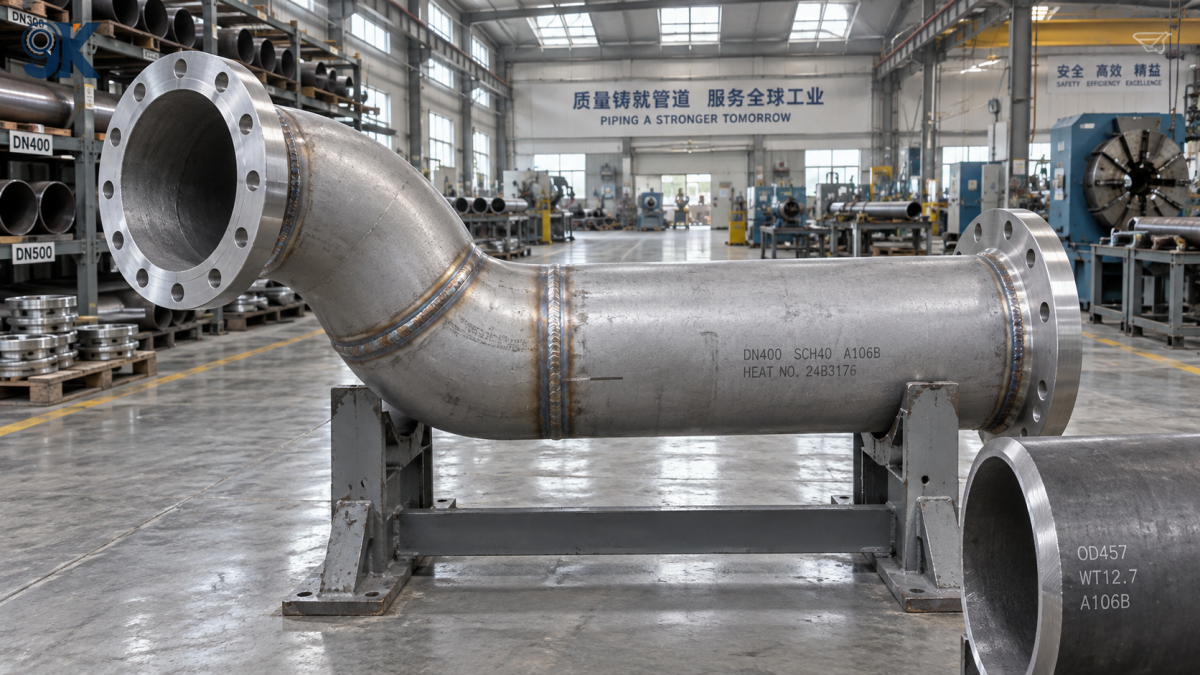
Prefabricated spools also need controlled orientation. A branch connection rotated incorrectly can make an otherwise dimensionally accurate assembly impossible to install. Drawings should show reference axes, flange orientation, branch positions, and identification marks that remain readable through handling.
Supporting fabrication sometimes includes ancillary metal products. For example, 304L Stainless Steel Wire could be specified for a separate tying or forming task within an equipment assembly. Such wire requires its own diameter, condition, and application requirements; its product name alone does not establish suitability as welding filler or as a pressure-retaining component.
Inspection connects the order to the delivered material
Quality verification should correspond to the specified service and manufacturing route. Basic dimensional inspection establishes outside diameter, wall thickness, length, straightness, and end condition. Visual examination identifies surface damage, poor end preparation, and other visible defects, but it cannot establish internal soundness or confirm material chemistry.
Material certificates provide documented results associated with the supplied material. Their value depends on traceability: the markings on pipes or bundles must connect to the relevant records. Once pipe is cut into shorter pieces, an agreed marking-transfer method preserves that connection. A certificate without a reliable link to the delivered pieces leaves a verification gap.
Different tests answer different questions:
- Chemical and mechanical testing establishes whether the tested material meets specified composition and property requirements. The sampling basis determines which production quantity those results represent.
- Ultrasonic, radiographic, magnetic particle, or liquid penetrant examination addresses particular discontinuities. Method selection depends on the material, component geometry, and defect type being investigated.
- A pressure test assesses performance under defined test conditions. It does not independently verify alloy identity, corrosion resistance, or every possible service condition.
Factory testing of individual pipes and pressure testing of an assembled piping system have different scopes. A pipe test does not verify field welds, flange assembly, valve installation, or the completed system boundary. Documentation should state what was tested, by which method, and against which acceptance criteria.
Inspection timing also affects rework. Dimensions and weld examinations that become inaccessible after assembly or coating need to be completed beforehand. Any required witness or hold points belong in the agreed inspection plan before production reaches those stages.
Surface treatment and packaging preserve the specified condition
External protection should match the exposure and the installation method. Indoor storage, outdoor weathering, buried service, and insulation create different conditions. A temporary transport coating should not be assumed to provide the long-term protection required after installation.
Coating quality begins with surface preparation. Rust, oil, moisture, and unsuitable surface texture interfere with adhesion. The required preparation, coating system, thickness, curing conditions, and repair procedure need definition. Where field welding is planned, coating cutbacks leave access at pipe ends, followed by treatment of the completed joints.
For stainless steel, handling practices should limit contamination from carbon steel tools, grinding debris, and shared storage surfaces. Pickling or passivation belongs in the scope when required by the fabrication condition and service specification. These treatments do not correct an unsuitable alloy selection.
Packaging must protect the features that matter to installation. End caps help exclude debris, flange-face covers protect sealing surfaces, and suitable supports reduce bending or impact damage. Clean-service pipe needs an agreed internal cleanliness level and preservation method; visible external cleanliness alone does not establish a clean bore.
Delivery includes identification and usable records
A complete delivery package connects each shipment to its technical and commercial records. Depending on the agreed scope, this includes packing lists, material certificates, dimensional reports, examination records, pressure-test records, coating reports, and fabrication drawings. Export movements also require shipping and customs documents with consistent product descriptions, quantities, and weights.
Shipment planning affects installation readiness. Delivering straight pipe without the matching fittings or prepared spools can leave a work area unable to proceed. Where installation follows a defined sequence, packaging and release schedules should reflect that sequence, with bundle or spool identifiers visible without extensive unpacking.
Transport length and lifting arrangements deserve attention before fabrication is finalized. Long assemblies can be difficult to load, secure, unload, or move through site access points. Dividing a spool for transport introduces additional field joints, which then require planned fit-up, inspection, and any necessary coating repairs.
The practical boundary of a steel pipe solution is established in the agreed scope: which components arrive, their finished condition, the evidence supplied with them, and the work left for site installation. Recording those boundaries alongside the drawings and material specifications makes differences between supply packages easier to identify before they become installation problems.
Latest News
- How anti-dumping duties change market access for steel pipe exports
- How Steel Pipe Warehousing and Logistics Affect Damage Rates and Delivery Costs
- Seamless vs Welded Steel Pipe: Which Option Fits Budget and Lead Time
- ASTM and EN Standards for Carbon Steel Pipe in Pressure Systems
- When a Standard Steel Pipe Works Better Than a Custom Specification
- What to Check Before Choosing a Steel Pipe Export Supplier for Your Market
Send Us A Message

