
Steel Pipe Processing: How Cutting and Welding Affect Dimensional Accuracy
Cutting and welding change the geometry of steel pipe, so dimensional acceptance must apply to the finished component as well as the incoming material. A pipe that meets its delivery specification can exceed assembly tolerances after an angled cut, uneven heating, or weld contraction. Reliable Steel Pipe Processing therefore requires defined measurement datums, controlled fabrication allowances, and inspection after the component has cooled and external restraint has been released.
Finished length, end squareness, straightness, and ovality need separate limits. Passing one measurement does not establish that the others are acceptable: a welded spool can have the correct overall length while its ends are misaligned, and an apparently round pipe can contain a local restriction near a circumferential weld.
Define the finished geometry before selecting the process
The first distinction is between a pipe product specification and a fabrication drawing. The product specification establishes requirements for the supplied pipe. It does not automatically define the acceptable position of a welded flange, the squareness of a machined end, or the alignment of two joined sections. Those characteristics need explicit drawing requirements or an agreed fabrication specification.
Measurement definitions matter as much as tolerance values. Overall length measured between the highest points of two rough-cut ends differs from length measured between fitted end planes. Likewise, straightness measured along an outside surface can include diameter variation, whereas the assembly requirement may concern the pipe axis. A dimension without a defined reference can produce conflicting inspection results.
Before fabrication, establish which surfaces or features locate the component in service. If a pipe fits between two machined shoulders, those shoulders should govern final length verification. If it carries bearing housings or aligned brackets, their relationship to the functional axis deserves more attention than the appearance of the outside surface.
Cutting errors begin at the end face
Squareness and kerf produce different length errors
An inclined cut creates a long side and a short side. Measuring only one side can accept a component whose average length is correct but whose mating face cannot seat properly. For a nominally circular pipe, the axial difference across the end is approximately the outside diameter multiplied by the tangent of the cut angle. The same angular error therefore produces a larger seating problem as diameter increases.
Kerf compensation addresses material removed by the cut; it does not correct blade wander or an inclined cutting head. Repeated parts that are consistently short suggest an allowance or reference-setting problem. Length that changes around the circumference points toward end-face angle, uneven thermal cutting, or inconsistent finishing.
A burr introduces another error. A tape, stop, or contact probe resting on a burr measures the projection rather than the intended end surface. Deburring belongs before dimensional acceptance, with care to avoid rounding the reference edge so heavily that the measurement location becomes uncertain.
Cutting method changes the source of variation
Thin-wall pipe requires particular care during clamping. A force sufficient to prevent movement can temporarily flatten the section. Machining while the pipe is distorted may leave an unacceptable shape after release, even when measurements taken in the fixture appear satisfactory.
Weld contraction changes length and alignment
A weld and its surrounding heated material expand during heating, then contract during cooling. Because the colder pipe restricts that movement, the resulting deformation depends on joint geometry, wall thickness, deposited weld metal, and restraint. A circumferential butt weld can shorten the assembly and alter the local diameter. Unequal contraction around the circumference introduces angular misalignment.
A longitudinal weld has a different relationship to the pipe geometry. Contraction across the joint influences circumference and roundness, while uneven contraction along its length contributes to bowing. Welding attachments onto one side of an existing pipe creates a localized heating pattern that can pull the pipe toward the attachment as the joint cools.
Heat input alone does not predict finished distortion. Welding speed, pass sequence, joint volume, interpass temperature, and the distribution of heat around the section also matter. A smaller weld volume generally reduces the amount of contracting material, but reducing the specified weld size or changing preparation without engineering approval can compromise joint performance.
Root gap is especially important in circumferential joints. An uneven gap changes the amount of weld metal required around the pipe and encourages asymmetric contraction. Forcing an irregular gap closed with clamps can store elastic strain that becomes visible only after release.
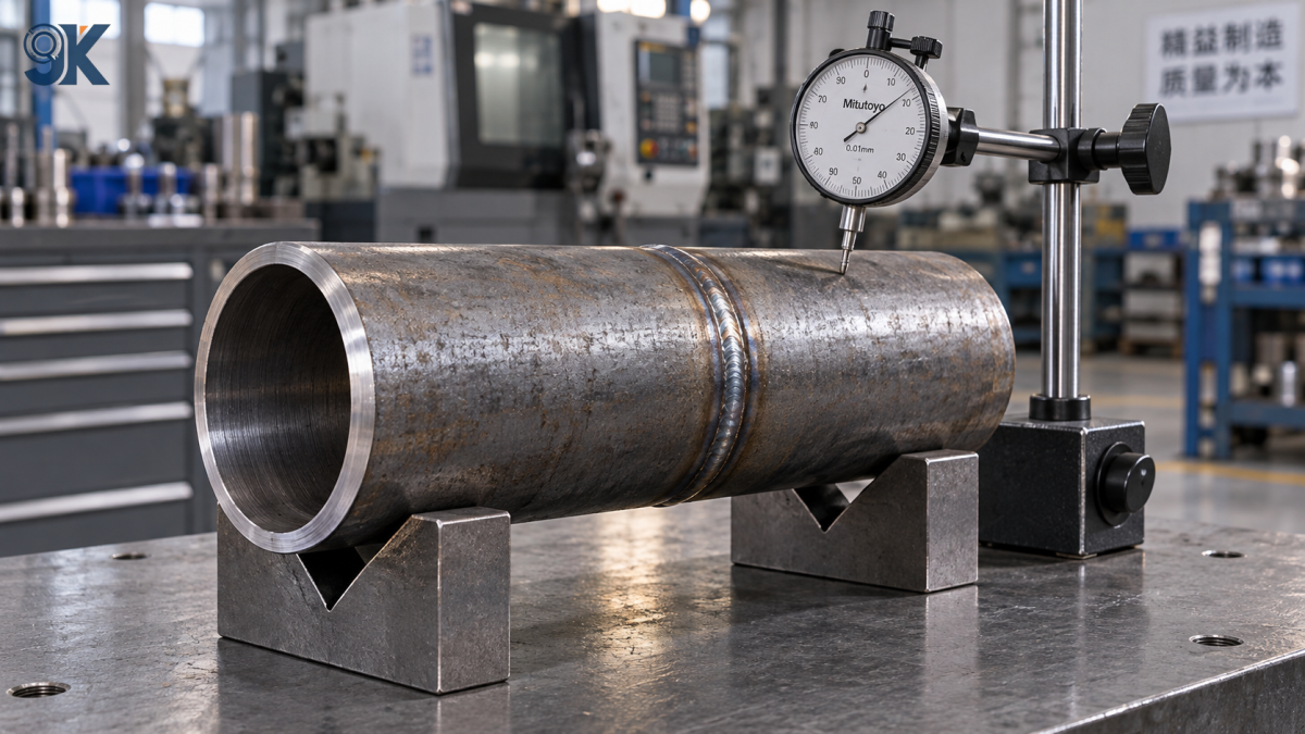
A useful process illustration shows the same assembly before tacking, after welding under restraint, and after cooling and release. Comparing these states separates distortion created during welding from movement previously hidden by the fixture.
Fixturing controls position but also changes the result
A rigid fixture holds the joint in position, yet restraint does not remove the thermal contraction that causes distortion. It changes how that contraction is accommodated, including the balance between movement and residual stress. Once the clamps are removed, the component can spring into a different shape.
Tack welds establish the initial joint geometry. Their location, size, and sequence influence whether the gap remains uniform as welding progresses. An assembly that starts with offset edges or angular mismatch requires correction before the main weld; additional weld metal does not reliably restore alignment.
Balanced welding sequences reduce the concentration of contraction on one side. Opposing segments or alternating locations can help where the joint design and welding procedure permit them. However, a sequence suitable for one diameter and wall thickness should not be assumed suitable for another. Changes in section stiffness alter the response to the same sequence.
Internal mandrels and external clamps also have limits. A mandrel can support roundness near a joint while leaving adjacent unsupported material free to deform. Excessive external clamping can mark or ovalize thin walls. Fixture contact locations and release conditions therefore belong in the process record when dimensional repeatability is critical.
Where internal purging is required by the material and welding procedure, temporary barriers must remain separate from the structural fit-up controls. Aluminum Foil used as a temporary purge closure does not establish alignment or root spacing; its suitability, placement, and removal require control to prevent contamination or retained debris.
Inspect at stages that reveal the source of error
Final inspection identifies acceptance, but intermediate measurements explain deviations. Recording incoming geometry, prepared-end geometry, fit-up, and released final dimensions makes it possible to distinguish an original pipe condition from a fabrication effect. Without that separation, a bowed assembly can be incorrectly attributed to welding when the starting pipe was already curved.
The most informative inspection points are:
- After cutting and edge preparation: record usable length, end squareness, and the condition of the reference edges. Include bevel geometry where it controls the joint gap.
- At fit-up, capture root gap around the circumference, edge mismatch, and relative axis alignment. These values establish the starting condition for welding.
- After cooling and fixture release: measure finished length and alignment under defined support conditions. Any subsequent straightening or machining requires another dimensional verification.
Roundness assessment needs more than a single diameter reading. Two perpendicular measurements can miss the largest and smallest diameters if the distorted section is rotated relative to those directions. Measurements at several angular positions, or a suitable profile measurement, give a better picture. Where ovality is expressed as a percentage, the calculation and reference diameter must be stated because different definitions produce different values.
Similarly, a straightness result depends on support spacing and orientation. Long, slender pipe sags under its own weight. Comparing a horizontally supported measurement with a differently supported inspection can confuse elastic sag with permanent bow. The inspection arrangement should reproduce the specified condition consistently.
Allowances must come from the actual fabrication route
Extra cut length is useful only when it corresponds to a defined later operation. An allowance for end machining differs from compensation for weld shrinkage. Combining both into an undocumented surplus makes it difficult to diagnose whether variation comes from cutting, joint fit-up, or welding.
Weld shrinkage allowances should be established from representative work using comparable material, diameter, wall thickness, joint preparation, welding procedure, and restraint. A single allowance transferred across different configurations offers little assurance. Where the finished length tolerance is tight, leaving controlled stock for machining after welding can provide a more predictable route, provided tool access and the component design allow it.
Temperature also affects close dimensional comparisons. A warm welded assembly is longer than the same assembly after cooling. Measurements taken at different temperatures require either stabilization at the agreed reference condition or a documented correction appropriate to the material. Local temperature gradients are particularly troublesome because a single surface reading does not describe the entire component.
The final acceptance record should identify the drawing revision, measured characteristics, datum references, support condition, and whether inspection occurred after release and any corrective processing. If a component achieves its specified geometry only while clamped, that condition must be explicitly compatible with the drawing and installation arrangement; otherwise, the released geometry determines acceptance.
Latest News
- How Steel Pipe Warehousing and Logistics Affect Damage Rates and Delivery Costs
- Seamless vs Welded Steel Pipe: Which Option Fits Budget and Lead Time
- ASTM and EN Standards for Carbon Steel Pipe in Pressure Systems
- When a Standard Steel Pipe Works Better Than a Custom Specification
- What to Check Before Choosing a Steel Pipe Export Supplier for Your Market
- Carbon Steel Pipe Grades Explained for Pressure, Temperature, and Corrosion
Send Us A Message

